Power Over Ethernet in a 5 1/4 inch bay.
Firstly the standard set of disclaimers...
"don't do this at home", "use only under adult supervision", "if illegal to do
so, do not modify any electrical device", "this WILL void your warrantee".
This page is to provoke an idea, not to teach you about network wiring or
electrical procedures. If you don't know what you are doing, ask someone
who does. Most of all, enjoy.
Problem:
I want to run an access point at the top of a 50 foot
pole and don't really want to run a power lead up there too. I also don't
want another bloody plug-pack transformer filling-up a power point in my office.
Solution:
Power over Ethernet (PoE) and get the power from the
PC that does the 802.11b wireless routing (this PC is always on when the
wireless access point is in use anyway).
Parts List:
1 x Flat double light switch
1 x 5.25 inch drive bay blank
2 x RJ45 sockets
1 x PC power socket
2 x nuts and bolts to suit
1 x cable tie
6 inches of CAT5 cable
Tools Required:
Hacksaw
Marker pen
screw driver / spanner to suit the nuts & bolts
"Stanley" knife (or sharp hobby knife)
Square drill-bit (approx 15mm)
Round drill bit to suit the nuts & bolts
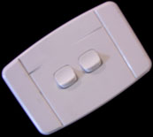
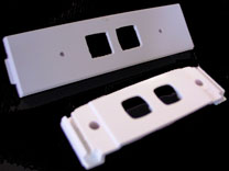
| 1. Start with a cheap, flat double
light switch. This one cost about US$3.00. Remove the two
switches, they should just clip-out leaving a mounting plate to suit
the RJ45 sockets. |
 |
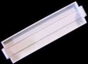
| 2. This is a 5 1/4 inch drive bay
blank. Yours may differ in looks but the size will be the same. |
 |
| 3. Using a hacksaw cut the switch
plate into a strip that will fit inside the drive bay blank. You
could use epoxy glue to mount the RJ45 "krone" sockets but in my experience it is
messy stuff and I would rather have a screw than end-up with messy goo all
over my hands. |
 |
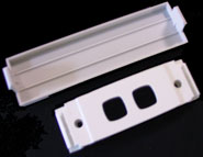
| 4. So now you should have two parts
that look like this. Next mark on the back of the drive blank where
the 4 holes should go. |
 |
| 5. Using your square drill bit cut the
two large holes in the face plate and using a standard round drill bit cut
two small-round holes for the screw mounting. |
 |
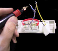
| 6. Wire it up. The standard
wiring for Cat5 is EIA-TIA 568a
and only the Orange and Green pairs carry signal. The blue and brown
pairs are free for us to run power over. If you dont have a "krone
tool" dont worry, the back of "stanley blade" will work ok too for a
"weekend hack" like us.
For wiring details see the end of the page
The POSITIVE (yellow) on power connector is soldiered to the brown
pair, the NEGATIVE (black) is soldiered to the blue pair. |
 |
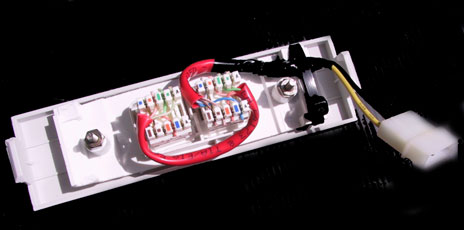
| Here you can see the two blocks "jumpered"
together to pass the signal (only the Orange and Green pairs are used).
The power connector has only the Brown and Blue pairs from the "Antenna"
side of the circuit. A cable-tie is used so that the wires are not
pulled out from the socket easily. |
 |
| |
|
You should have something that looks
like this now! The only things left to do are to label the face
plate so you know which has the "injected power" and the most important
part of the project... TEST IT BEFORE YOU PLUG IT IN. Use a
multimeter or even a torch battery and light globe to test the pin-outs
before plugging an expensive computer and access-point into this.
#### USE AT YOUR OWN RISK #### |
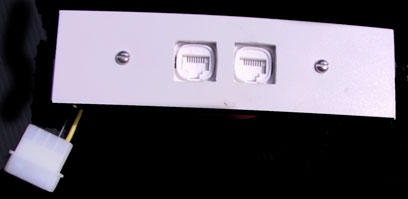 |
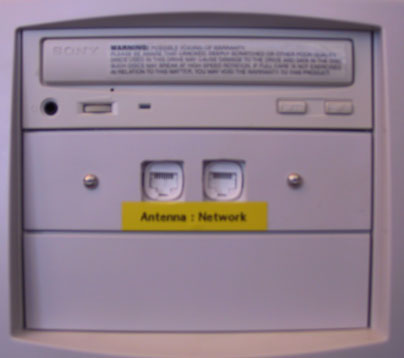
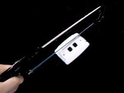
The end result looks like this in my
"wireless server".
Where do the wires go?
|
ANTENNA SIDE |
NETWORK SIDE |
| 1 White & Green |
1 White & Green |
| 2 Green |
2 Green |
| 3 White & Orange |
3 White & Orange |
| 4 Blue (NEGATIVE 12V to BLACK on the socket) |
4 not used |
| 5 Blue & White (NEGATIVE 12V to BLACK on the socket) |
5 not used |
| 6 Orange |
6 Orange |
| 7 Brown & White (POSITIVE 12V to YELLOW on the
socket) |
7 not used |
| 8 Brown (POSITIVE 12V to YELLOW on the socket) |
8 not used |
This is a picture of the plug (and not the socket)
You can see from the above table that pins 4,5,7,8 are the ones
that carry the 12V power. At the access point end you should be able to
modify the RJ45 socket so that pins 4&5 run to negative and pins 7&8 run to
positive on the access points power socket.
I "modded" a Compaq WL400 access point by "patching" the
underside of the RJ45 socket to the factory power socket. I was lucky that
the WL400 is designed to run with a fairly broad power input, you would be wise
to make sure that your access point can run with 12V or risk the chance of
"blowing it to bits". The above PoE 5.25 inch hack worked well for me!
This page URL is:
http://kawasaki.kz/wireless/poe.htm
Created: 12 March 2002
By:
Andy Freeman